
Rectangular Carbon Fiber Tubes: Check Corner Clearance Before Sampling
Check the complete section and mating profile before sampling a rectangular carbon fiber tube. Define corner clearance, engagement length and acceptance evidence.

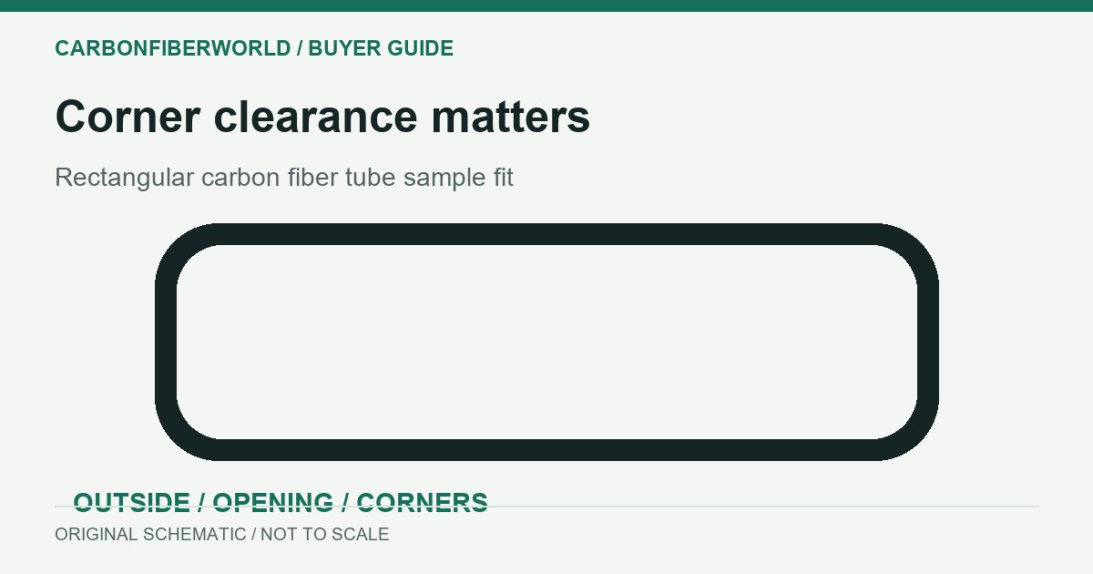
A rectangular carbon fiber tube needs more than a width and height to define a reliable fit. Specify the outside and inside profiles, corner geometry, mating component and engagement length together. Then agree how the sample will be checked. Two sections can share the same nominal width and height while presenting different space at the corners.
This guide helps buyers prepare a tube-and-interface enquiry. It does not prescribe a universal clearance, approve a joint design or establish the load capacity of a supplied tube. The drawing owner must set the functional requirements and acceptance limits for the complete assembly.
What does the catalogue size actually define?
Start by identifying whether the listed dimensions describe the outside section or the opening. CarbonFiberWorld lists CFW-3117 with a nominal 30 × 50 mm outside section and CFW-3114 with a nominal 50 × 80 mm outside section. Neither outside size, by itself, defines the inside profile, wall requirement, corner radius or fit tolerance.
A flat-wall thickness can help describe a section, but subtracting twice that thickness from the outside dimensions does not fully describe a rounded opening. The inside corners still need a defined shape. Do not replace that missing information with a sharp-corner rectangle drawn from nominal numbers.
Supplier documentation supports keeping these items separate: Rock West Composites’ stock tube tolerance sheet directs readers to individual product details for corner-radius information. Its values apply to that supplier’s stock products, not to a CFW order.
Why can the corners prevent an insert from fitting?
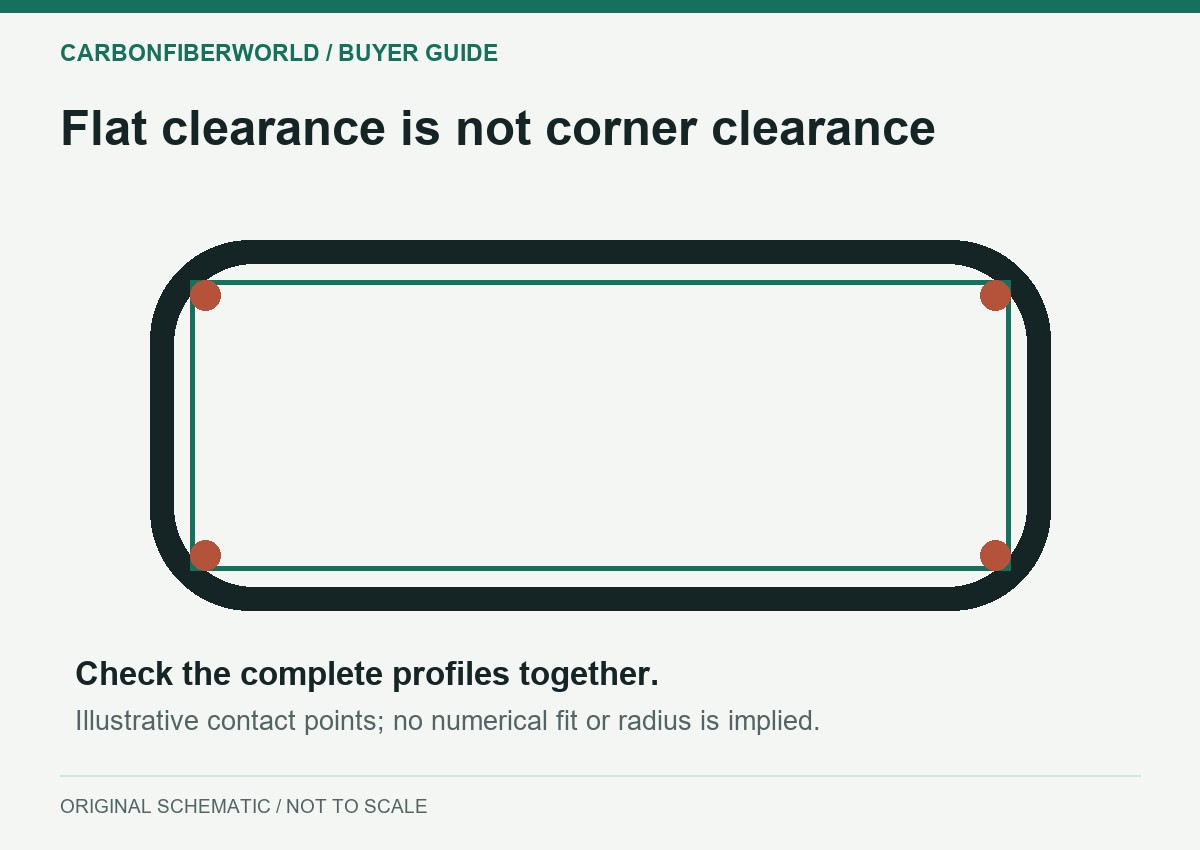
An internal insert must fit within the complete opening, including the corners. Checking only the distance between opposite flat walls can miss interference where the insert’s corner meets the tube’s inside curve. Describe the insert profile and the tube opening in the same section view.
For illustration, imagine an insert whose flat-to-flat dimensions leave space between the tube walls. If the insert has nearly square corners and the tube opening has more rounded corners, that space along the flats does not prove corner clearance. A radius, chamfer or other relief on the mating component may change the fit, but the design owner must specify and approve it.
C-Tech’s rectangular tube documentation identifies inner radius with tooling and describes a relationship between wall thickness and outer radius for its own products. This is a useful example of why corner geometry belongs in the enquiry; it is not evidence of a particular CFW radius or tooling capability.
Separate the inside fit from the outside mounting face
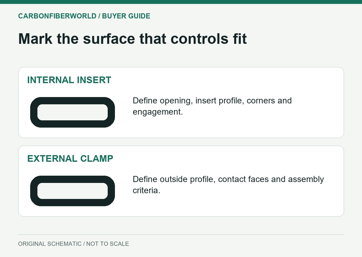
An insert, an external clamp and a flat bracket contact different parts of a rectangular tube. Mark the surfaces that control the intended interface rather than applying one unspecified “tube tolerance” to every feature.
| Interface | Information to put on the drawing | What a nominal section leaves open |
|---|---|---|
| Internal insert | Opening profile, insert profile, corner relief and engagement length | Whether corners clear and whether the insert reaches its intended position |
| External clamp | Outside profile, contact faces, corner clearance and assembly requirements | Where the clamp contacts the tube and how the finished assembly is accepted |
| Flat bracket or end plate | Reference face, orientation, hole or cut-end features and mating envelope | Whether the installed features align with the rest of the assembly |
Also identify which face corresponds to each section dimension. Keep that orientation consistent in the end view, length view and assembly drawing. Include coatings, bonded regions or other finished conditions when they affect the interface. Do not infer a safe clamping force, adhesive gap or joint strength from section size.
ASME’s description of Y14.5 explains the role of dimensioning and tolerancing in communicating form, fit and function. State the drawing convention used by your project; an enquiry note should not silently mix different interpretation rules.
Plan a sample check that tests the intended fit
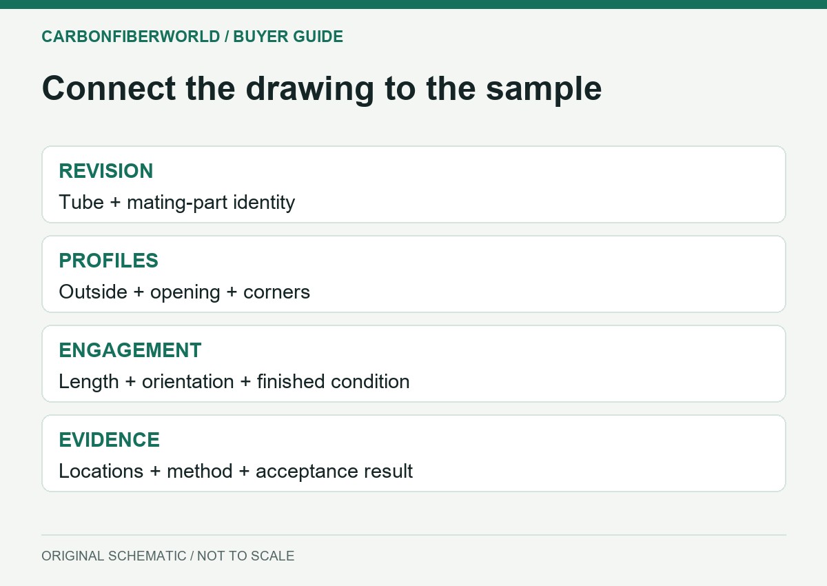
The sample plan should connect a dimensional check to the actual mating requirement. A section measurement records geometry; a controlled trial assembly checks a specified pairing. Keep both records tied to the same drawing revision, sample identity and mating-component identity.
- Freeze the section view. Show the outside and inside profiles, critical corners, reference faces and the mating part. Mark unresolved dimensions as open.
- Define the length involved. State the intended engagement length and where section geometry will be evaluated. A check at the cut end alone does not establish clearance through a longer engagement.
- Agree the finished condition. Identify whether the check concerns an unfinished sample or the final supplied surface and end features.
- Specify the evidence. Agree the dimensions, locations, method and any profile or fit-check record needed. Do not assume a particular instrument or inspection document is included.
- Record the assembly result. Identify the actual mating part or agreed gauge, orientation and acceptance criterion. Log any exception and the revision it affects.
If the part enters at the end but stops before the agreed engagement, record where it stops and which surfaces contact. That is a reason to investigate the complete profiles and the agreed evaluation extent, not to force the assembly or assume that sanding the tube is acceptable.
A fit check does not prove load capacity or durability. Use the specification and inspection planning guide to separate nominal information, agreed requirements and actual results. Where bow or alignment matters along the length, the straightness and runout guide addresses a different part of the acceptance plan.
Send one section-and-interface package for quotation
A useful rectangular-tube enquiry includes the tube section and its mating component together. Send the following information so the supplier can review the same fit problem:
- Product reference or required section shape, with outside dimensions clearly identified.
- Inside profile and wall requirements, with corner details or the critical clearance envelope.
- Tube length, engagement length, orientation and reference faces.
- Mating-part drawing, revision and finished condition.
- Assembly purpose, relevant load directions and environmental requirements.
- Sample quantity, order quantity, destination and requested acceptance evidence.
If a corner value or mating requirement is still undecided, identify it as an open design item. Ask what can be reviewed and confirmed before sample approval rather than treating an unlisted value as a supply promise.
Review the custom carbon fiber tube options, then send your section and mating-part drawings for a quotation review. Reference CFW-3117 or CFW-3114 when using those listed outside-section configurations.
Illustrations are original editorial schematics, not photographs of CFW products, customer assemblies or inspection results. Shapes are explanatory and not to scale. Primary references were reviewed on October 3, 2026; supplier-specific geometry and tolerances remain specific to the cited supplier.