
Telescopic Flagpole Ground Sleeve Fit: An OEM Buyer Checklist
Check telescopic flagpole ground sleeve fit with a practical interface record for model, geometry, engagement and retention before an OEM order.

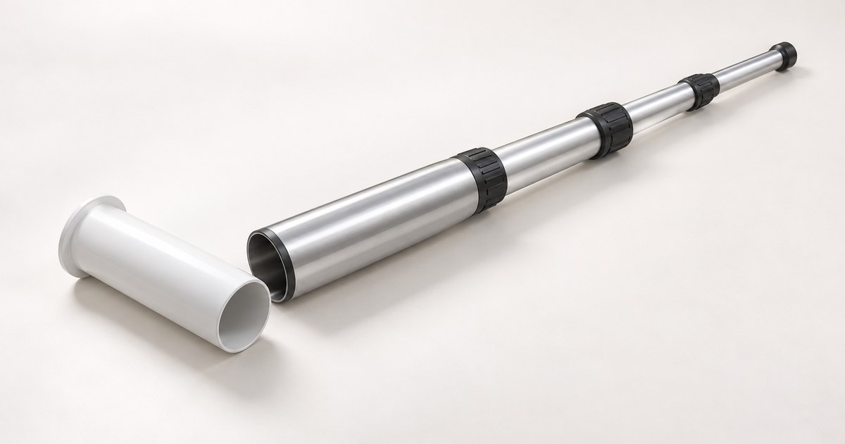
To check telescopic flagpole ground sleeve fit, match the selected pole’s insertion-end geometry to the sleeve’s usable opening, engagement depth and locating or retaining features. Overall height and the word “aluminum” do not establish compatibility. Record the exact model or drawing revision, how the pole stops and stays in place, and who approves the installation before ordering.
This guide helps distributors, event operators and procurement teams prepare an interface brief. It is a purchasing checklist, not a foundation design or installation manual. Use the selected system’s instructions and the responsible installer’s site assessment for installation and operating limits.
Start with the installation you actually have
An existing sleeve and a new installation need different information. For a replacement pole, identify the installed sleeve and its original system before asking whether a new pole will fit. A photograph of the opening is useful context, but does not establish its internal dimensions, depth or hidden stop arrangement.
For a new installation, ask the supplier to identify the intended mounting system and its matching parts. Then have the installer confirm suitability for the site. Keep the pole-to-sleeve interface separate from the sleeve-to-ground or bracket-to-structure design: a successful dry fit cannot approve the foundation.
- Reuse an existing sleeve: provide its identity, usable dimensions, relevant features, condition and available original instructions. Record any uncertainty before selecting the replacement pole.
- Order a new matched system: request the pole, sleeve or other mount, locating parts, retention hardware and instructions as an itemized package.
- Change mounting method: request a separate compatibility review. A sleeve, ground spike, crossbase and fixed bracket are not automatically interchangeable.
Why matching the diameter alone is insufficient
Manufacturer instructions show why the complete interface matters. Telepole’s installation index distinguishes different generations of telescoping hardware. Its linked ball-bearing-system instructions describe bottom notches engaging a sleeve stop bolt and a separate set-screw alignment. Those features belong to that system; they are not specifications for a CFW pole.
Flagpole Farm’s Titan sleeve-clamp instructions require the clamp to contact the matching ground sleeve. A clamp designed for one sleeve should not be treated as a universal adapter.
A different example appears in Valley Forge Flag’s fiberglass telescoping-pole instructions: they describe a bottom mounting hole for a temporary mount and a separate permanent sleeve arrangement. This is a useful counterexample to assuming all telescopic poles use the same interface. It is not evidence that CFW supplies those components.
The purchasing conclusion is to document both the dimensional fit and the locating or retention arrangement. Do not transfer a different manufacturer’s hole sizes, engagement lengths, foundation dimensions or wind limits to the model being ordered.
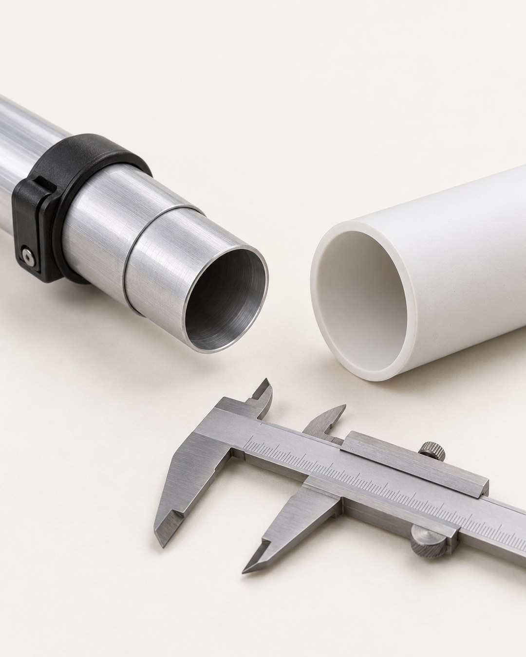
A reusable pole-to-sleeve interface record
Copy these fields into the RFQ or drawing review. Use measured or supplier-confirmed values where available; mark unknown fields explicitly. This record is original editorial organization, not a test report or industry standard.
- Identity: pole model or controlled drawing, sleeve or mount reference, revision and photographs of the selected interfaces.
- Pole insertion end: outside dimensions at the mating region, shape, steps or taper, surface finish and any locating notches or holes. State where and how the dimensions are checked.
- Sleeve opening: usable inside dimensions, internal depth, obstructions and condition. Do not substitute an outside sleeve dimension for its usable opening.
- Engagement and stop: the intended inserted length, stop arrangement and finished sleeve position, as defined by the selected system. Ask who controls each requirement.
- Retention: identify the specified clamp, pin, screw or other retaining arrangement and the matching features. Confirm whether these parts are included and replaceable.
- Operating configuration: required pole height, flag dimensions and quantity, accessories, site location and intended use. Request applicable model-specific limits and instructions.
- Installation responsibility: name the party who approves the mounting design, site conditions and installation. Record any unresolved interface or installation questions.
- Release evidence: agreed drawings, matching-part list, sample fit observations, instructions, deviations and the person authorized to approve the package.
No universal clearance value is specified here. The appropriate fit depends on the particular system and its retention method. Obtain the selected manufacturer’s requirements rather than creating a clearance from a photograph or a generic buying guide.
Review a sample before committing the installation
Arrange a controlled fit review of the identified parts before embedding a new sleeve or accepting a replacement assembly. Follow the selected system’s handling instructions; this guide does not ask you to raise an unsupported pole or make an improvised load test.
- Check that the sample identifiers and revision match the quotation and interface record.
- Confirm the intended mating region, stop and retention features can be assembled as instructed; record the actual observations.
- Check that the required components and instructions are present. Separate missing accessories from a dimensional mismatch.
- Document any binding, unexpected movement or feature mismatch for the supplier’s review. Do not drill, trim or substitute retaining parts without an approved change.
- Obtain the installer’s separate approval for site mounting. Sample fit approval does not establish wind performance, foundation capacity or electrical safety.
Agree the acceptance criteria and who signs off before the sample arrives. Keep a dated approval record, the final parts list and any approved deviations for repeat orders.

Prepare a flagpole quotation with a clear supply boundary
CarbonFiberWorld lists an Aluminum Telescopic Flagpole, reference CFW-2879. The published listing identifies the material and product form; height, mounting, flags and accessories are confirmed for the selected configuration. Do not infer that a sleeve, foundation, bracket or particular retention mechanism is included from a generated illustration or the product URL.
For an enquiry, send the interface record, installation location, required height, flag configuration, quantity and destination. Ask for a quotation that separates the pole, mounting components, flags, accessories and packing. Where existing parts will be reused, identify them and request explicit compatibility confirmation.
Keep artwork approval alongside this mechanical review. Our custom event flag artwork proof checklist covers the printing handoff, while the flags and banners range helps identify the commercial package.
Ready to discuss a configuration? Send your flagpole requirements with reference CFW-2879. Include unresolved sleeve or mounting questions so the quotation can state what is confirmed and what still needs review.