
Carbon Fiber Tubes with Printed Scales: Agree the Reference Point Before Ordering
A six-step buyer guide to locating the scale zero, choosing units and direction, defining the installed reading edge, and approving tube geometry and print artwork separately.

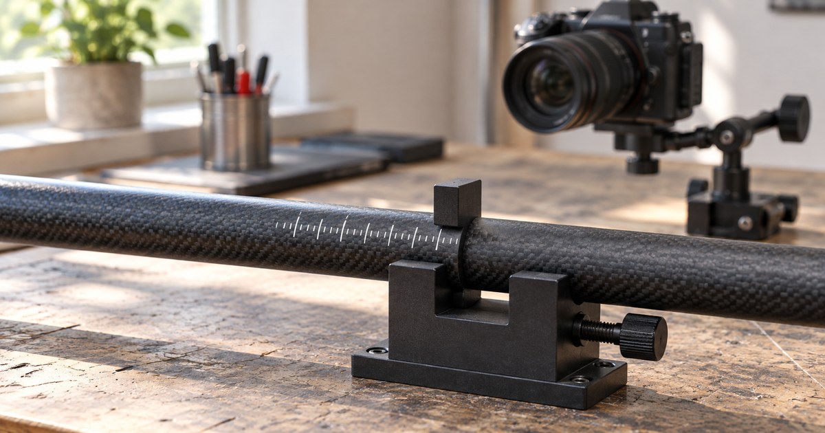
Picture a camera-positioning bench: a round tube slides through a guide, and an operator looks at its printed marks before choosing a position. A second person checks the same tube from the other end. Unless the drawing identifies the zero, reading edge and direction, they may understand those marks differently.
For a carbon fiber tube with a printed scale, agree what each mark refers to before approving the order. Tube length, print zero and the installed reading edge are three separate decisions. A useful specification connects them in an annotated side view and end view, then controls the tube drawing and print artwork together.
The CFW-3022 printed-scale tube listing describes a round hollow tube with a printed scale to specification, providing a visible position or length reference. The camera support in this guide is an illustrative setting; its hardware and suitability require their own project review.
Illustrative positioning scenario.
1. Put the zero against a named physical reference
Start by naming the tube end or assembly feature from which the scale is defined. “Zero at the end” is incomplete when either end could be used, or when the assembly stops the tube somewhere else. Label the ends A and B on the side view and identify the selected end face.
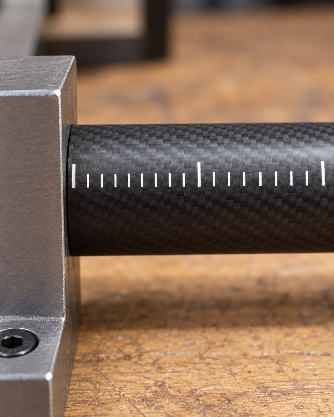
If the intended reference is End A, show where the zero mark sits relative to that face. A print margin can place the first visible mark away from the cut edge. State the intended relationship rather than assuming that the first mark means zero at the tube end.
If the reference is an assembly stop face, show that face on the assembly sketch and locate the printed zero relative to it. The stop face and the tube end need not coincide. Ask the drawing owner to specify any required offset and its acceptance requirement. This defines the reference; it does not approve the stop, fit or connection design.
2. Choose the units and the increasing direction
Write the unit on the artwork and state what the scale indicates: distance from the named reference, an extension position, or another defined quantity. A row of numbers without that description leaves the reader to supply the meaning.
Choose millimeters, inches or another agreed unit explicitly. If a project needs two unit systems, treat both scales as artwork that needs review. Do not silently change units or round values when producing another version.
Add an arrow showing the direction in which values increase, with End A and End B still visible. Define the intended range, tick spacing and labeled values, then ask the supplier to review the proposed print layout. The presence of printed ticks does not establish a calibrated measuring instrument. If numerical accuracy matters, the buyer must specify the requirement, verification method and evidence to discuss for the order.
3. Draw the reading edge in the installed arrangement
The reading edge is the feature against which a user reads the printed scale. It might be the edge of a guide or a separate pointer in the proposed assembly. Name that feature on the sketch instead of expecting the operator to choose a convenient edge.
The scale zero and reading edge have different roles. The zero defines the scale’s origin; the reading edge selects the mark being read when the tube is installed. Changing the selected edge can change the reading without changing the tube or artwork. For procurement, record the relationship between the two.
Use the end view to show which side of the round tube carries the print. Include the intended viewing side and number orientation. A side view alone may leave the print’s position around the circumference unclear. Show whether the tube’s orientation is controlled in the assembly, and identify any locating feature for review. The listing does not include a camera, clamp, guide or anti-rotation device simply because a scene depicts one.
4. Check what stays visible during adjustment
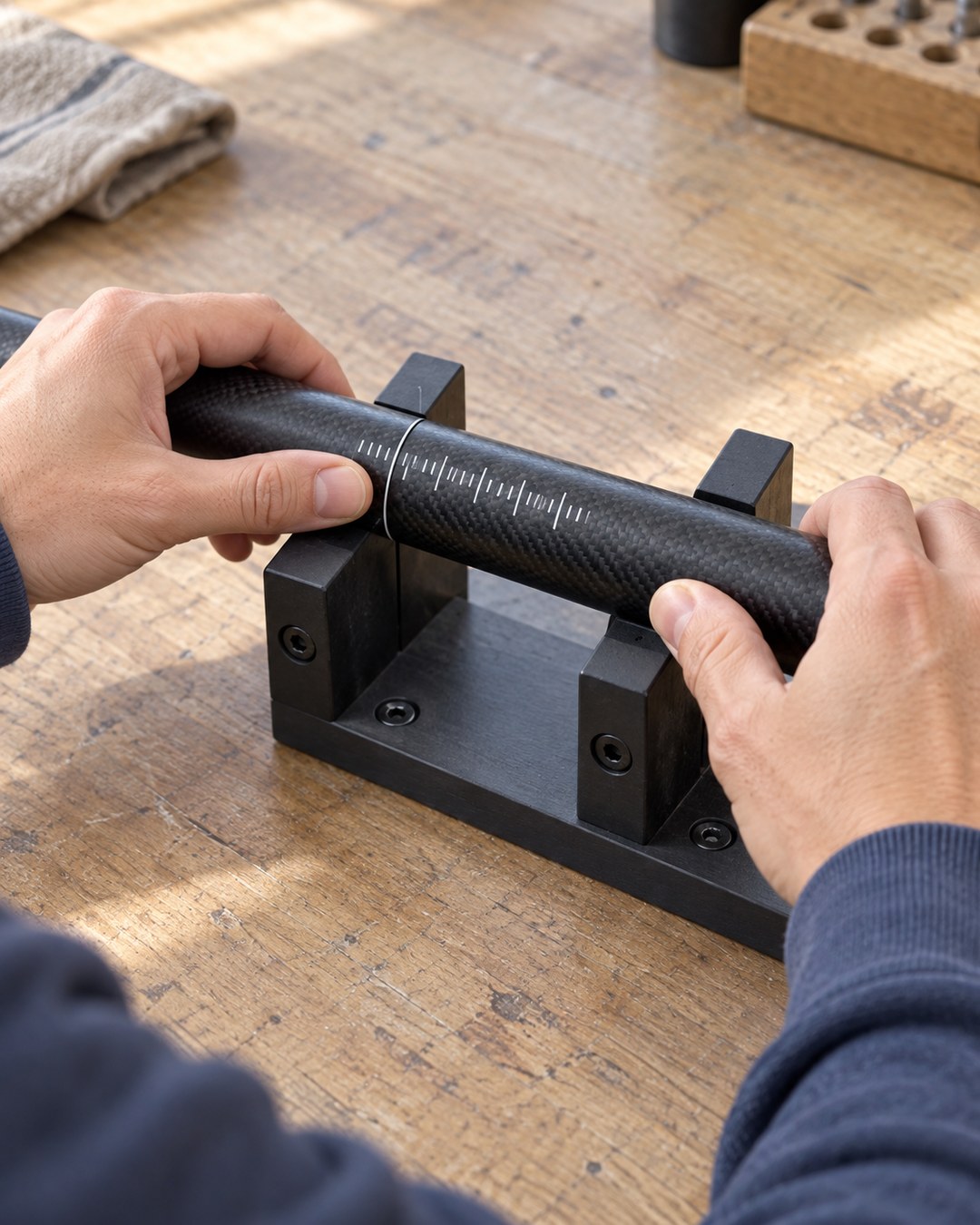
Review the proposed reading range with the guide, clamp or adjacent equipment shown in place. Identify which marks must remain visible and whether the unit and direction can still be understood at those positions. A full-length scale can be clear on a loose tube while the installed arrangement hides the part the operator needs.
Keep print placement and viewing conditions in the same discussion. Specify the required printed area, number orientation and appearance, including any proposed contrast requirement. Ask which layout can be agreed for the chosen tube surface. If the guide contacts or covers the printed area, raise that condition for review rather than assuming the marking has a particular wear resistance.
A mock-up or sample photograph can help the parties discuss visibility. Request a view from the intended reading position, with the sample and revision identified. Such an image documents appearance; it cannot by itself establish numerical accuracy or performance under use.
5. Give geometry and print their own approval records
Keep the tube drawing and scale artwork identifiable as separate controlled files. The geometry document defines the outside and inside dimensions, finished length, end features and agreed requirements. The artwork defines the zero relationship, units, direction, tick layout and print position. Both need revision references so the approved pairing is clear.
| Review area | Decision to agree | Evidence to request for that decision |
|---|---|---|
| Tube geometry | Which dimensions and features define the supplied tube? | Identified sample and the dimensional checks agreed for its drawing. |
| Printed scale | Does the proposed marking match the approved layout and reference? | Identified artwork revision, print sample and agreed marking checks. |
| Installed use | Can the chosen reading edge and visible range serve the application? | Assembly arrangement and any separately agreed functional evaluation. |
Approve the print proof for the decisions it actually supports. A proof can establish the intended wording and layout; a sample can support the agreed physical marking checks. Neither automatically releases the tube’s structural requirements or the completed camera support. Record open items and who will resolve them before approval.
Use the custom tube specification guide for the underlying tube requirements and the specification and inspection planning guide when agreeing the evidence needed for release. If the zero, end feature or artwork changes later, identify the affected approval rather than relying on the old photograph.
6. Send one annotated enquiry package
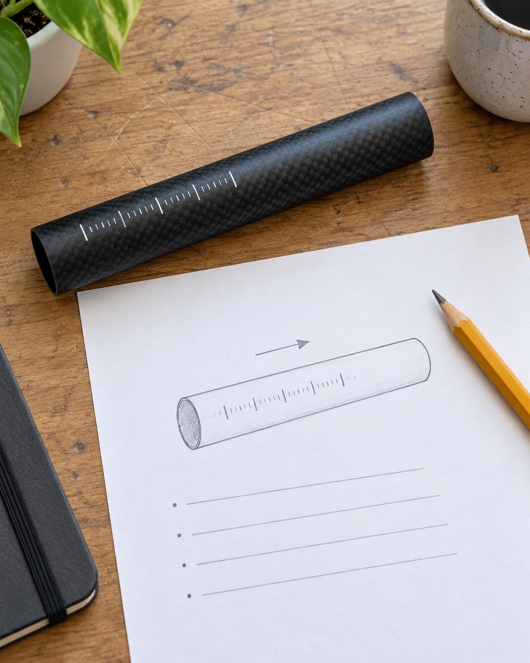
Prepare a side view showing End A, End B, the selected reference, zero relationship and increasing direction. Add an end view for print position and a small assembly sketch showing the reading edge and required visible range. Attach the controlled tube drawing and artwork references rather than scattering decisions across unrelated messages.
For an enquiry about CFW-3022, include the tube section, finished length, intended application, quantity and destination, together with the scale units and proposed marking layout. Identify the equipment you will supply and any additional work you want reviewed. The quotation should confirm the agreed tube, print and scope of supply.
Start the tube-and-print enquiry through the contact page. Describe the reference-point decisions in your message and arrange a suitable channel for drawings and artwork. A named zero, a named reading edge and an approved file pairing make the next discussion specific.