
Slotted Carbon Fiber Plates: Define the Usable Adjustment Range
A slot's outside length does not establish assembled adjustment. Separate overall length, fastener-centre travel and actual clearance before agreeing the drawing.

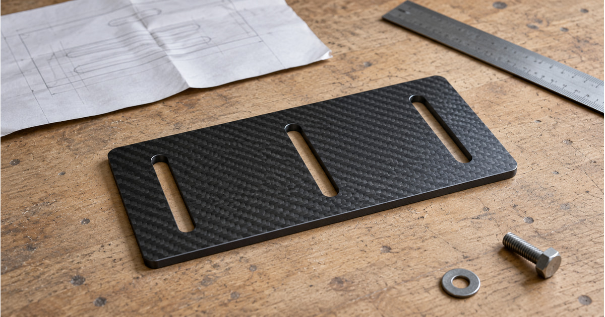
A slot’s overall length is not the usable adjustment range of an assembled part. First separate the slot geometry from the path a fastener can follow. Then check whether the attached bracket, a second fixing point or nearby equipment stops the movement earlier. For a slotted carbon fiber plate enquiry, specify the required assembled positions and how they will be checked, alongside the slot dimensions.
This guide is for buyers and designers reviewing a drawing before quotation or sample approval. The numerical example below is hypothetical geometry, not a measurement or specification of a CarbonFiberWorld product.
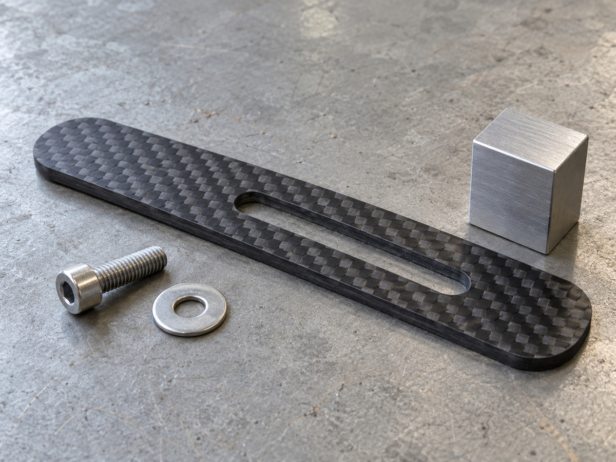
Scene images are generic editorial illustrations, not CFW product photographs.
Separate three dimensions before discussing travel
A drawing can describe a round-ended slot by its outside length or by the distance between the centres of its rounded ends. Those dimensions are different. Autodesk’s slot creation guide distinguishes overall and centre-to-centre slot construction; the buyer and supplier should agree which dimension the drawing uses.
- Overall slot length, L: the distance between the two outermost ends.
- End-centre spacing, C: the distance between the centres of the semicircular ends.
- Fastener-centre travel, T: the maximum end-to-end movement of the fastener’s centre along the slot centreline under the stated geometry assumptions.
The assembled adjustment range is a further requirement. It concerns the positions the complete arrangement can actually reach and use.
Work through one hypothetical slot
Assume a straight slot with parallel sides and matching semicircular ends. Its overall length is 24 mm and its width is 6 mm. A perfectly round, 4 mm diameter shank passes perpendicular to the plate and moves along the slot centreline. These are chosen example dimensions, not a recommended fit or an actual M4 fastener measurement.
With exact ideal geometry, no extra end clearance, no deformation and no surrounding obstructions:
C = L − W = 24 − 6 = 18 mm.
T = L − D = 24 − 4 = 20 mm.
The shank centre stops half its diameter before each outer slot end. Subtracting those two end distances from the overall length gives the 20 mm centre travel. The 18 mm spacing between the rounded-end centres is a different quantity. This is the ideal axial limit for the shank alone, not an approved operating range for the assembly.
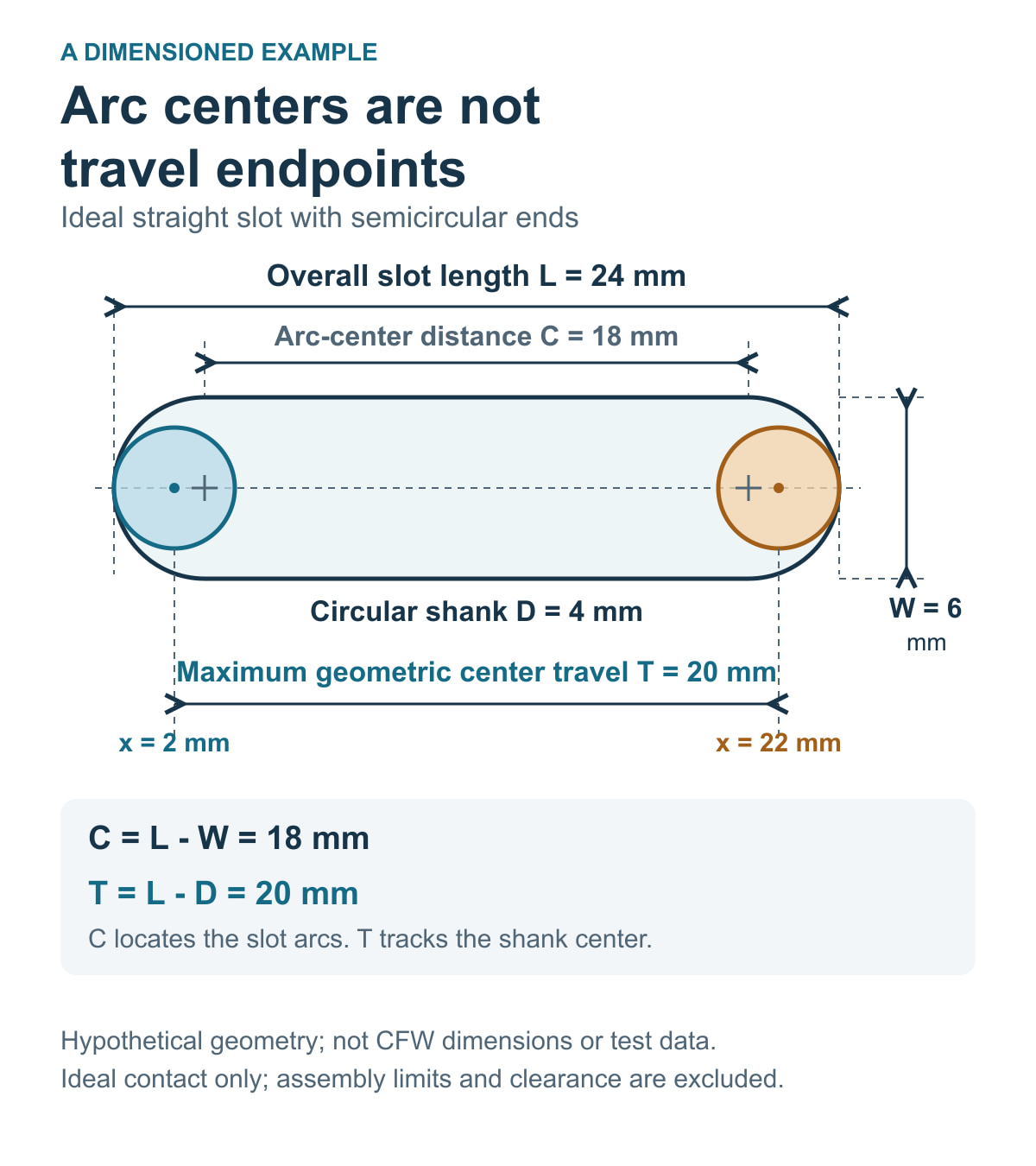
This calculation describes one ideal geometrical limit. A real drawing must account for actual feature sizes, tolerances, required clearance and the rest of the assembly. It establishes neither load capacity nor a suitable tightening procedure.
Check what moves with the fastener
Review the complete moving group, not just the shank inside the slot. A bracket may meet a raised edge before the shank reaches the rounded end. A cable, another fixing point or a tool-access requirement may also restrict the usable positions.
A plain washer on an unobstructed, suitable support surface does not automatically shorten the shank’s geometrical travel. Do not simply subtract the washer diameter from the slot length. Check the washer and fastener head against actual walls, steps, mating parts and the required bearing arrangement throughout the movement.
| Question | What to record |
|---|---|
| Which length is on the drawing? | Identify overall length or end-centre spacing, with slot width and drawing revision. |
| What must move? | Identify the bracket or component, the motion direction and the reference datum. |
| What may restrict movement? | Check nearby features, other fixings, cable routing and access across the required range. |
| Which positions are acceptable? | Define required start and end positions, clearance allowances and the agreed check method. |
Put the assembled requirement on the drawing
Instead of writing only “adjustable slot,” show the required start and end positions relative to an identified datum. State whether adjustment is for initial alignment or repeated repositioning. Identify which fasteners are loosened or removed during that operation and which other connections remain fixed.
Supply the mating-part drawing or an assembly view when another component can limit travel. Keep the slot geometry, assembled movement requirement and acceptance method distinguishable. A drawing can then show precisely what needs confirmation without turning a calculated range into a production guarantee.
For related feature details, use the guide to holes, countersinks and inserts. That is a separate question from whether the complete assembly reaches its required positions.
Use an assembly release record
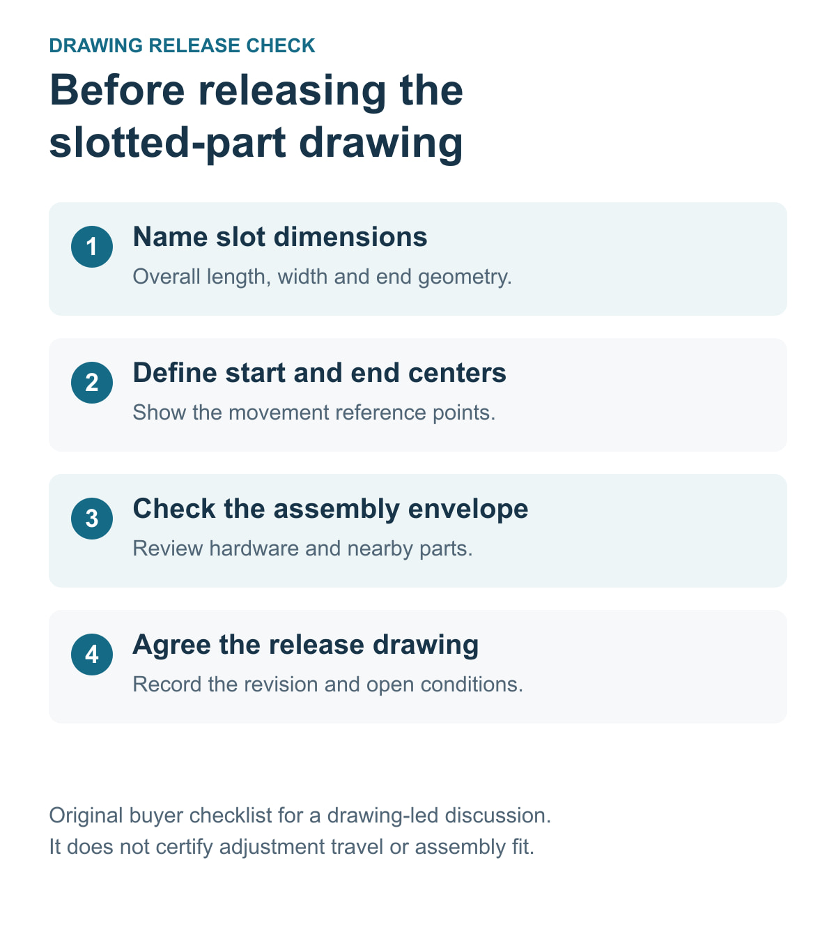
Keep this proposed record with the sample or drawing review. Unchecked items remain open; a completed checklist is not a substitute for the agreed physical inspection.
- Identity: part reference, plate drawing revision and mating-part revision.
- Geometry: slot length convention, width, position and relevant tolerances.
- Hardware: actual shank dimensions, head and washer arrangement, and other fixing points.
- Required movement: datum, direction, start position, end position and clearance allowances.
- Assembly check: parts and hardware used, method, observations and any inaccessible or restricted position.
- Decision: accepted, revise or not checked, with the responsible reviewer and date.
Send a requirement that can be quoted
The CFW-3196 slotted carbon fiber CNC plate listing identifies carbon fiber laminate parts whose opening and slot details follow the agreed drawing. The enquiry asks for slot widths and lengths, centre-hole size and edge condition. It does not supply the hypothetical dimensions or assembled travel used above.
Send CarbonFiberWorld your drawing and assembly requirements, including the enquiry reference, laminate and thickness requirements, required positions, quantity and destination. Include mating parts and the proposed release record so the quotation can identify what is confirmed and what still needs agreement.
Prepared by CarbonFiberWorld. Product pages and editorial sources reviewed on 21 October 2026. This is a drawing and assembly planning guide; no CFW physical test results are presented.