
Non-Round Carbon Fiber Tubes: Define the Installation Orientation
A seven-field drawing handoff record for defining the end, viewing direction, section reference and feature relationships of a non-round carbon fiber tube.

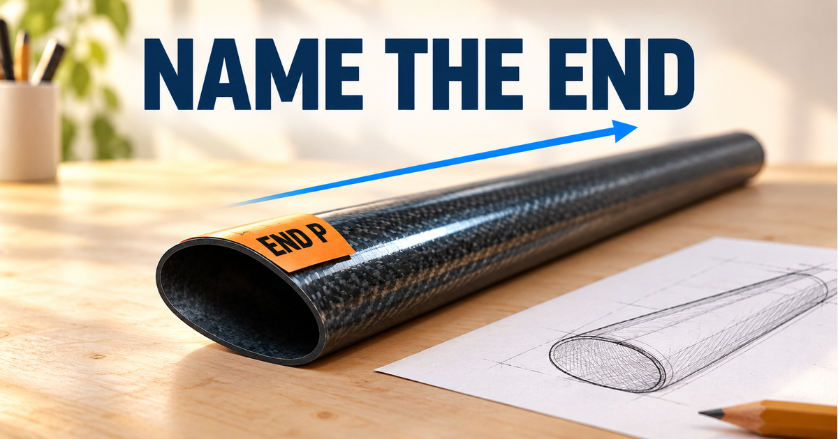
A non-round carbon fiber tube’s section dimensions do not fully define its installed orientation. For a tube with orientation-sensitive interfaces, identify the reference end, the viewing direction and the section reference, then locate each relevant feature from those same references. A hole, slot or end connection can be described clearly in one view and still remain ambiguous in the complete assembly.
This guide helps OEM buyers prepare drawings for quotation and sample review. It does not choose a structural design, prescribe a geometric tolerance or establish that a particular machining operation is included in a CFW tube offer.
Decide whether orientation affects the delivered part
Start with the part you are buying. A plain tube blank and a finished component with a side opening or an end fitting are different deliverables. Show downstream interfaces when they explain the requirement, but identify which features belong in the supplier’s scope and which will be added elsewhere.
Not every tube needs a special clocking requirement. If the design owner confirms that reversing the section or exchanging equivalent faces does not affect the assembly, record that decision. Extra reference marks should resolve a functional ambiguity rather than create an unnecessary inspection demand.
Where orientation does matter, the section outline is only the starting point. An unmarked oval outline can look unchanged after a half-turn, while a feature on one side moves to the other side. A regular hexagonal outline likewise has repeated faces. The shape name alone cannot identify the intended functional side.
Name the end before naming left and right
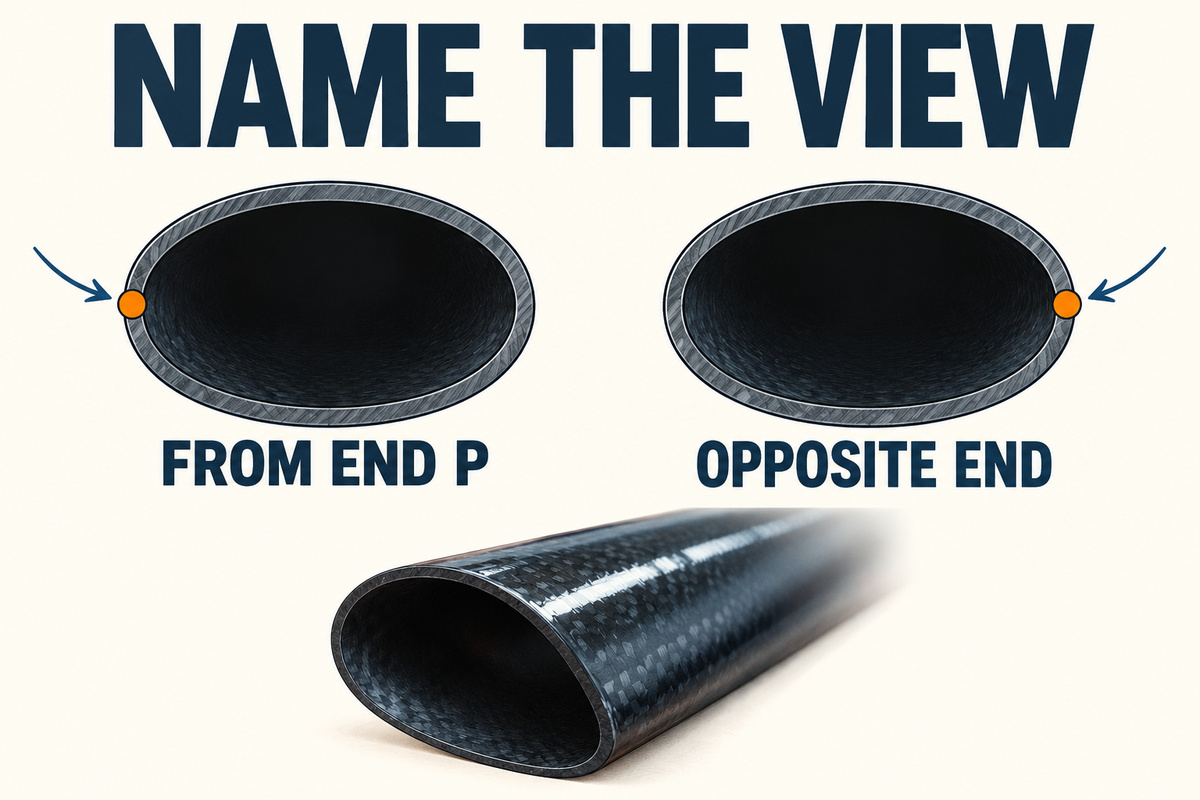
Give the two ends unambiguous identifiers on the enquiry drawing. In the example below, End P is a temporary identification label, and the common end view is described as looking from End P toward the opposite end. These words establish how the example is read; they are not a formal GD&T datum designation.
A person viewing the tube from its other end sees a different projection. A feature described only as “on the right” can therefore be interpreted differently by two people facing opposite ends. Use an explicit viewing direction and the drawing’s projection conventions. Opposite-end views are useful when labelled and related correctly; they should not silently share an undefined left/right instruction.
ASME’s public Y14.5 description explains the role of consistent rules for interpreting engineering drawings and digital definitions. The responsible drawing owner should select the applicable convention, datum scheme and tolerance requirements for the actual component.
Connect the section reference to every functional feature
For an oval section, show which section direction must align with the assembly. For a flat-sided profile, identify the relevant face or reference geometry rather than assuming that everyone chooses the same face. Then connect that reference to the features that affect installation.
This is a different requirement from fiber orientation. An external profile direction or visible weave does not define the internal laminate. Keep the construction requirement separate from the geometric relationship between the tube and its mating parts.
KEYENCE America’s explanation of datum systems shows how combined references establish relationships for toleranced features. For an enquiry, the practical task is to make the intended relationships readable; the final drawing still needs an appropriate engineering definition.
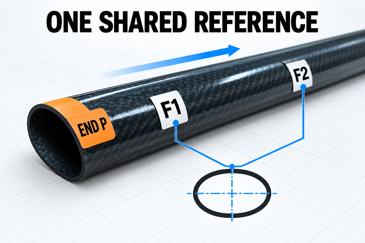
Locate features both along the tube and around its section. A longitudinal distance from End P does not, by itself, identify the side on which a feature belongs. Conversely, a named side does not establish its distance from the end. Where an angular relationship is necessary, show it using the released drawing’s references and agreed limits, rather than inferring it from a perspective rendering.
Use one orientation handoff record
Keep the following record beside the drawing and quotation. It is an original purchasing aid, not a replacement for a dimensioned drawing or an inspection report. The example identifiers describe a hypothetical part and do not represent a CFW product specification.
| Record field | What to identify | Example of a clear entry |
|---|---|---|
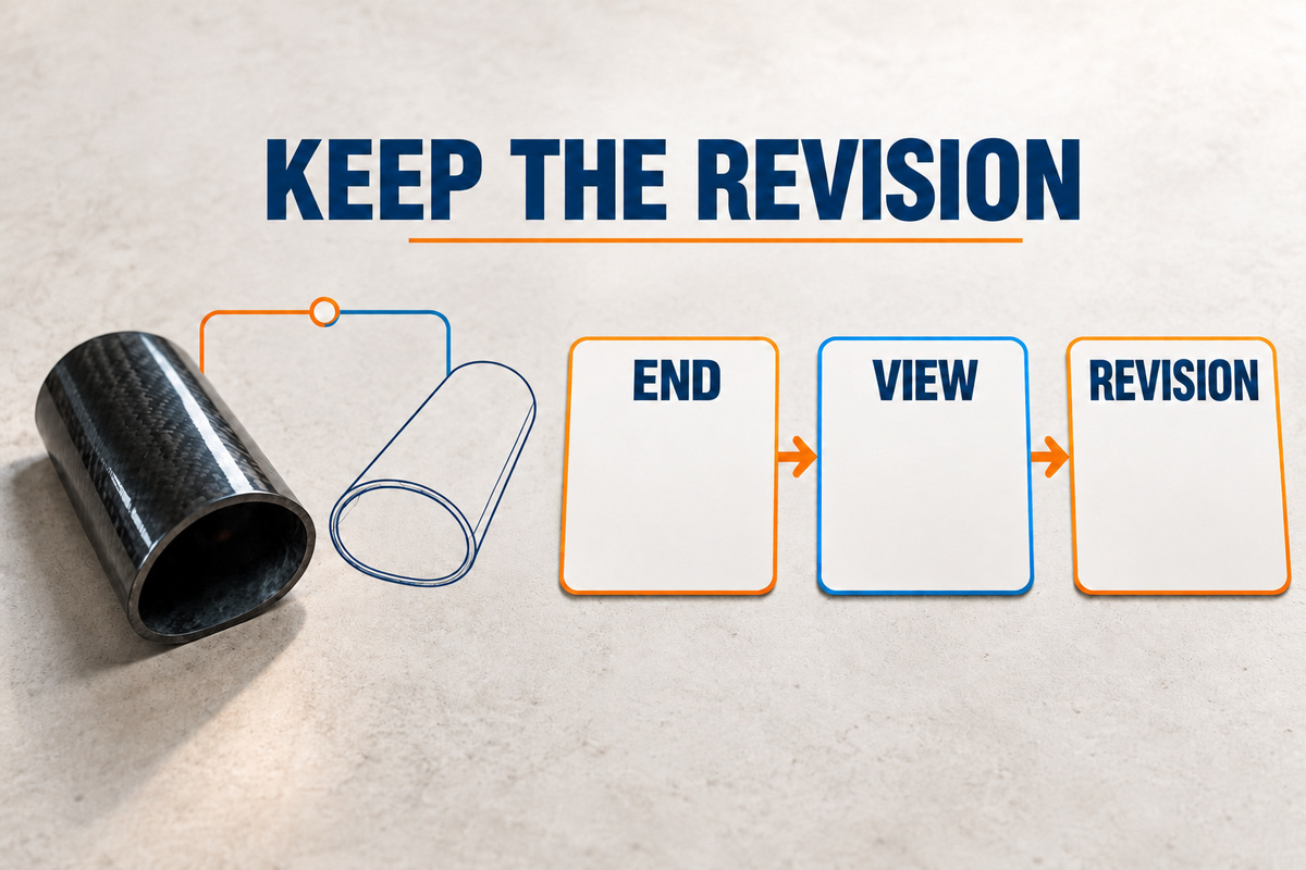
| Part and revision | The tube detail, assembly drawing and current issue | Use the same released revision in the enquiry, supplier response and approval record. |
| Named end | The physical end used for the longitudinal reference | End P is labelled in the tube detail and assembly view. |
| View direction | Where the observer looks from and toward | Common end view: looking from End P toward the opposite end. |
| Section reference | The face, axis or plane selected in the engineering definition | Link the named section reference to the assembly orientation; do not use the page’s “top” alone. |
| Feature and longitudinal position | Each interface identifier and its position from the stated end/reference | Features F1 and F2 each point to their dimensioned position on the same tube detail. |
| Feature direction and supply scope | The side or angular relationship, plus who supplies the feature | Show F1 and F2 relative to the section reference; identify downstream features separately from the supplied tube. |
| Approval ID and evidence | The reviewed drawing, sample identity, check method, result and any exception | Record the approval identifier and the exact revision it accepts; keep unresolved relationships open. |
Before accepting the quotation, compare its scope with this record. If the supplier offers a plain blank while the assembly drawing shows later machining, the quotation should make that boundary clear. Do not assume that the presence of a feature on an assembly view means it is included in the tube price or supply.
Review related features together on the sample
Consider a hypothetical tube with two orientation-sensitive interfaces, F1 and F2, at different positions along its length. One sample photograph shows F1 from End P; a second shows F2 from the opposite end without stating the change. Both photographs can look plausible while leaving their relative direction unresolved.
Return to the common reference definition. Identify the actual sample, document the views and check the relationships required by the released drawing. Do not replace an unresolved relationship with an assumed rotation, or approve two isolated photographs as evidence that the complete installed orientation is correct.
KEYENCE’s fixturing guidance describes the connection between drawing references, stable positioning and comparable inspection. Agree the sample’s support or restraint condition and the checking method with the responsible parties. This guide does not specify a clamping force, fixture design or universal angular limit.
Record any mismatch against the exact feature and revision. If a drawing change resolves the ambiguity, review the affected interfaces before releasing the revised requirement. A correctly identified direction still does not prove structural capacity, joint strength or service suitability.
Prepare the CFW enquiry around the intended deliverable
The CFW-3124 oval carbon fiber tube listing is a starting point for a shaped-section enquiry. CFW also lists a hexagonal tube reference, CFW-3120. Confirm the required section, construction, finished condition and scope of supply for your project; the profile name is not a promise of a particular tolerance or machining service.
For opening geometry and mating-part clearance, use the separate rectangular-tube corner-clearance guide. For axial form and rotation-based checks, see the straightness and runout guide. Those questions remain distinct from identifying which way the installed features must face.
Send an orientation-defined tube enquiry with reference CFW-3124. Include the current tube and assembly drawing references, named end, view direction, section reference, feature positions and directions, required supplied condition, quantity and destination. Put CFW-3124 in your message, describe any unresolved item and agree how supporting drawings will be shared with the team.
The orientation record and hypothetical examples are original editorial synthesis. Illustrations are explanatory, not to scale, and are not photographs of a CFW model, a customer assembly or a measured sample. External drawing and measurement guidance was reviewed October 21, 2026.