
Quasi-Isotropic vs Unidirectional Carbon Fiber Plate: What the Drawing Must Specify
A buyer-side guide to choosing between quasi-isotropic and unidirectional carbon fiber plate and documenting the laminate, fiber direction and acceptance evidence.

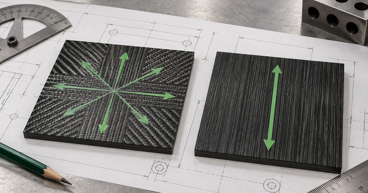
Direct answer: unidirectional carbon fiber plate concentrates most reinforcement along one named axis. A quasi-isotropic laminate distributes reinforcement among several in-plane directions. Neither label is a universal property guarantee: the material system, ply angles, stacking sequence, thickness, machining orientation and acceptance evidence still need to be controlled.
For a buyer, the drawing should do more than say “UD” or “quasi-isotropic.” It should define the 0° reference, the controlled laminate or approved supplier construction, the finished geometry and tolerances, visible faces, machining direction where relevant, and the records needed to approve the first article. This guide helps prepare an RFQ for a carbon fiber sheet or plate or a CNC-cut part. The responsible engineer must approve the laminate and load path for the real assembly.
Why “carbon fiber plate” is not a complete material specification
Carbon fiber composites are direction-dependent. Fiber orientation changes how a laminate carries load, while resin, fiber type, cure, ply sequence and thickness also affect the result. A unidirectional material can be efficient when the main load direction is known and controlled. A multi-angle laminate can distribute reinforcement across more than one in-plane direction. The word “quasi-isotropic” describes an intended directional arrangement; it does not make a composite identical to an isotropic metal.
A visible twill or plain-weave surface also does not prove the internal layup. The cosmetic face may be only one layer over a different core construction. Procurement should therefore separate appearance requirements from the structural laminate definition.
Quasi-isotropic versus unidirectional: the buying decision
| Question | Unidirectional plate | Quasi-isotropic plate |
|---|---|---|
| Main design intent | Reinforcement concentrated along a named primary axis | Reinforcement distributed among several in-plane directions |
| Drawing priority | Show the 0° fiber direction relative to datums, holes and load path | State the approved stacking sequence or controlled laminate specification |
| Common purchasing risk | Part is rotated or nested without preserving the required fiber direction | “Quasi-isotropic” is accepted without defining the actual construction |
| Appearance risk | A surface layer is mistaken for the primary reinforcement direction | A decorative weave is mistaken for proof of a balanced multi-angle laminate |
| Evidence to request | Material identity, orientation record and first-article dimensional evidence | Controlled layup reference, material identity and first-article evidence |
1. Establish the coordinate system and the 0° reference
Use a drawing datum, edge or coordinate axis to define 0°. State whether that direction follows the long part axis, a load path or another controlled reference. For a CNC-cut part, include the fiber-direction requirement in the released drawing package so nesting or stock rotation cannot silently change the intended orientation.
Do not rely on a rendering arrow without a note. Tie the arrow to a datum and revision-controlled requirement. If more than one ply orientation matters, use the approved laminate schedule or specification rather than a single surface arrow.
2. Define who controls the laminate
If engineering owns the laminate, list the approved material system and stacking sequence using the organization’s drawing conventions. If the supplier may propose a construction, state the required design inputs and require the proposed layup to be documented and approved before production. “Supplier standard quasi-isotropic plate” is only useful when the exact standard, revision and evidence are identified.
Terms such as balanced or symmetric should appear only when the engineering requirement and the referenced construction support them. They should not be added as generic quality language. Likewise, do not substitute a fiber datasheet value for a finished laminate property; first-party data sheets commonly distinguish constituent or typical material data from guaranteed part performance.
3. Separate structural construction from visible weave
Mark the visible face, gloss or matte requirement, permitted print-through and any cosmetic exclusion zones separately from the laminate schedule. If the surface weave direction matters visually, define it as an appearance requirement. That keeps a decorative face from being interpreted as structural evidence and prevents an internal layup requirement from being judged only by appearance.
4. Control finished geometry and machining orientation
State the finished thickness, profile, datums, hole locations, tolerances and edge condition needed by the assembly. The previous CFW guide on choosing carbon fiber sheet thickness explains why thickness should follow the finished part and support conditions. For holes, countersinks and inserts, use the separate fastener-feature specification guide.
When fiber direction affects cutting layout, make it a controlled drawing requirement. Do not assume a supplier will infer the intended orientation from the longest edge or from the CAD model. Release the STEP or DXF geometry together with a dimensioned PDF that carries the material, orientation, tolerance, surface and revision notes.
5. Agree the first-article evidence before the order
The RFQ should say what evidence closes each requirement. A practical package may include the material or batch identity, recorded orientation, approved laminate reference, dimensional report, visual inspection of the specified face and confirmation of drawing revision. Add tests only when they are defined and relevant to the real configuration; a generic coupon or a supplier brochure does not automatically validate the finished part.
| RFQ item | Buyer provides | Supplier confirms |
|---|---|---|
| Part identity | Part number, revision, quantity and intended assembly | Exact revision used for quotation and manufacture |
| Coordinate system | Datums and 0° reference | How orientation is maintained through cutting and inspection |
| Laminate control | Exact schedule or performance inputs and approval route | Proposed controlled construction and traceable reference |
| Appearance | Visible face, weave alignment and acceptance zones | Available finish and inspection method |
| Geometry | Finished dimensions, tolerances, holes and edge requirements | Manufacturing and dimensional inspection plan |
| Approval evidence | Required reports, samples and change-control rules | Records supplied with the first article and repeat orders |
Short answers for drawing and purchasing teams
Is quasi-isotropic carbon fiber truly isotropic?
No. A defined multi-angle laminate can approximate a more even in-plane response than a unidirectional laminate, but it remains a layered composite. The exact layup and material system govern its behavior, and through-thickness behavior is different from in-plane behavior.
Can surface twill prove the internal layup?
No. A woven cosmetic face does not establish the orientation or sequence of the internal plies. Request the controlled laminate reference and acceptance evidence separately from the appearance specification.
Should the drawing list every ply angle?
If the buyer’s engineering controls the laminate, the released specification should define the approved sequence. If the supplier controls the construction, the drawing package should still define the design inputs, approval route, material identity and evidence required before production.
Prepare a clearer carbon fiber plate enquiry
Review the current CFW sheet and plate range and the specification and inspection guide. Then use the contact page to send the drawing, 0° reference, laminate requirement, visible-face notes, quantity and first-article evidence needed. CFW can compare the request with its current supply and machining scope without turning a general material label into an unsupported performance promise.
Source note: Prepared from current CFW public pages; Toray terminology and composite material data guidance; Hexcel laminate technical data; NASA technical records on fiber orientation and quasi-isotropic laminate behavior; and ASME Y14.5/Y14.45 drawing-practice references reviewed on 30 September 2026. Search volume, keyword difficulty, rankings, Google Trends and AI prompt volume were not measured. The image is original AI-generated editorial artwork.