
CNC Carbon Fiber Part Sets: Confirm Left and Right Hand Before Ordering
Define common or handed CNC carbon fiber parts, installed views, file revisions and quantities. Use a release checklist before ordering a component set.

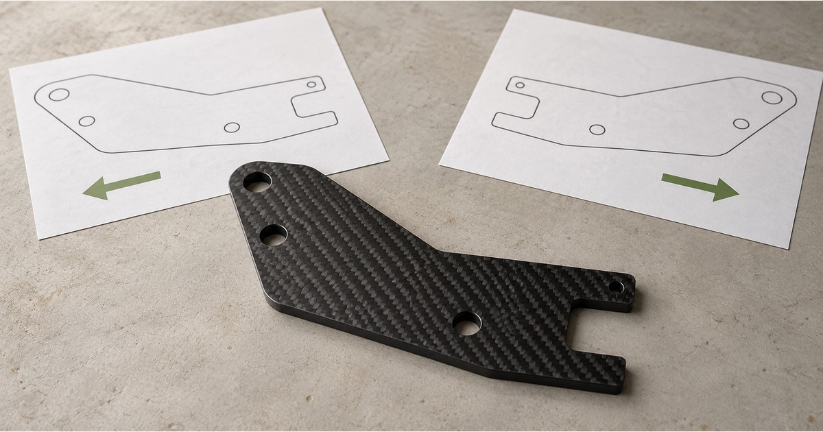
Before ordering a set of CNC-cut carbon fiber parts, decide whether the assembly uses one common part in two positions or two separately identified handed parts. Then tie each ordered item to a drawing, revision, installed view and quantity. A mirrored picture alone does not settle that decision, and an undefined “pair” can conceal a missing component.
This guide is for engineering and purchasing teams releasing flat-profile component sets. CarbonFiberWorld’s CFW-2795 custom CNC-cut parts page is the commercial starting point. The agreed drawing defines the supplied components; this article does not qualify a joint, prescribe a laminate or confirm an unreviewed design.
The images are original editorial illustrations and an editorial checklist, not photographs of an exact supplied model, production drawings or inspection records.
First decide: common reversible part or separate handed parts?
Start with the actual assembly rather than the names in an email. Can the same physical part be installed in both required positions while satisfying every drawing and assembly requirement? If the design owner confirms that it can, the order may use one common part identity with a larger quantity. If it cannot, define the two variants separately.
For a flat component, turning the part over can reverse the apparent outline in a photograph. That does not by itself prove interchangeability. Check the required face, any features confined to one face, finish or marking requirements, and the specified laminate orientation. Do not approve a flipped installation from the outline alone. Keep unresolved design questions with the responsible engineer.
CAD terminology also needs care. SOLIDWORKS describes an opposite-hand version as a derived-part use case, with a reference relationship to its source. That is different from merely viewing an unchanged part from another direction. For procurement, ask which final part definition the supplier is being asked to make.
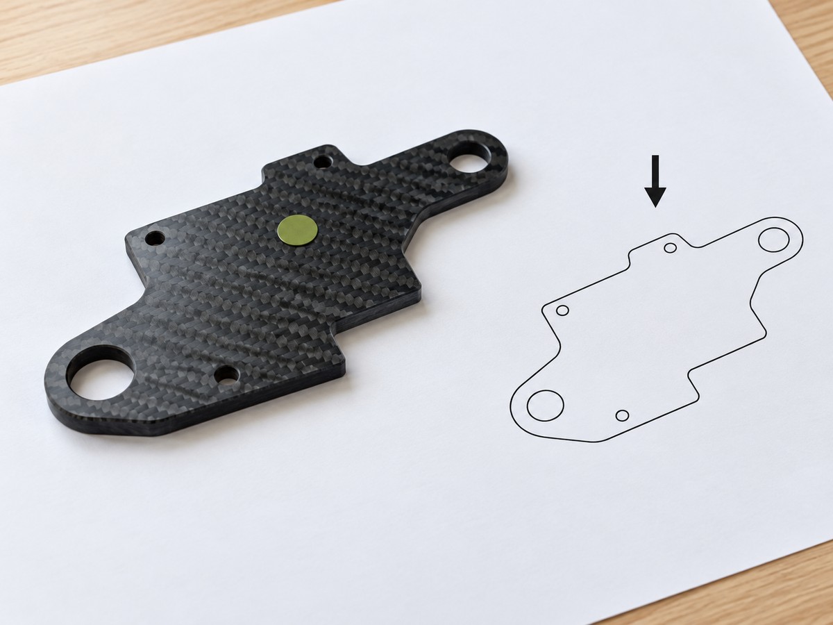
Agree the installed view and the required face
“Left” and “right” need a reference. State the viewing direction in the assembly document: for example, the agreed front view of the installed unit. Show a recognizable assembly reference and identify the component face used for approval. A photograph taken from the opposite side should not silently reverse the order-line names.
- Show the component in its intended installed position, with the agreed viewing direction.
- Identify any required visible face and any face-specific feature or finish on the controlled drawing.
- State whether the counterpart is a separate part or a confirmed alternative installation of the common part.
- Ask the supplier to flag any inconsistency between the assembly view, part file and purchase description.
A removable sample label can help a discussion, but its position is not a new manufacturing datum. Specify any permanent marking and its permitted location separately. Do not assume that the supplier will add identification to a cosmetic or functional surface.
Release each part identity with its own current files
Use an unambiguous mapping between the purchase line, part number, CAD export and dimensioned drawing. If the two hands have separate identities, provide the released definition for each. A filename containing “mirror” is not enough to establish which revision was quoted or approved.
Where a CAD model derives from another file, review what a parent-model change does to its counterpart before releasing new exports. Confirm the revision of both ordered items after a change. Do not assume that a CAD relationship has automatically updated an already exported file, an attached PDF or the supplier’s saved quotation.
The separate hole, countersink and insert specification guide covers individual interface definitions. Use it for those feature requirements; keep the handed-part record focused on identity, installed orientation and which components complete the set.
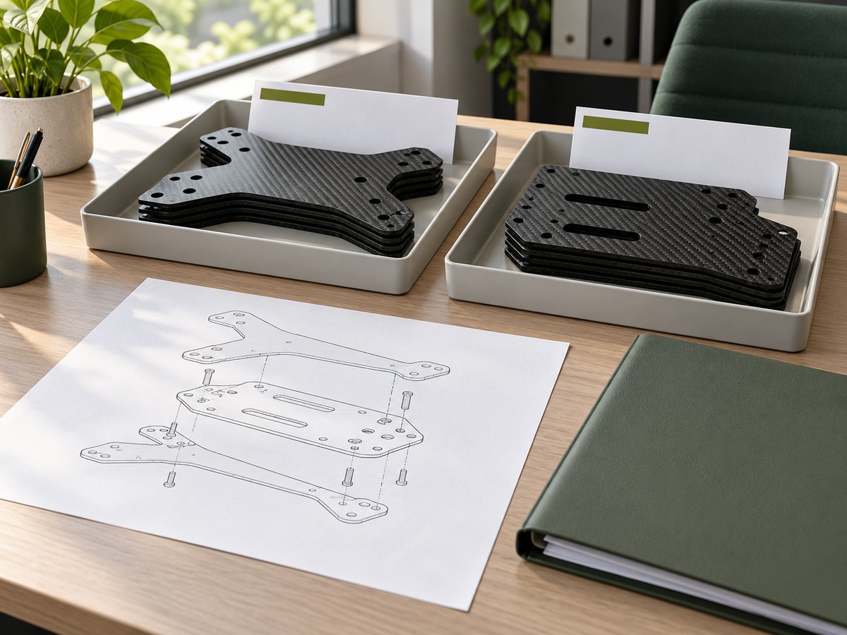
Count pieces by identity before using a set total
State how many of each identified component one assembly requires, how many assemblies are being ordered, and which additional pieces are spares. Use “set” only after its contents are defined. Matching the total number of pieces does not establish that the mix is correct.
Illustrative counting example: if an agreed assembly needs one left-hand plate and two right-hand plates, ten assemblies require ten left-hand and twenty right-hand pieces before spares. This is a hypothetical arithmetic example, not a CFW kit or minimum order. A request for “ten pairs” would not communicate that configuration.
List spares against the same part identity and revision. Also state whether components should arrive grouped by assembly or separated by item. These are requirements to agree, not promises about a standard packing or inspection service.
A handed-component release record buyers can adapt
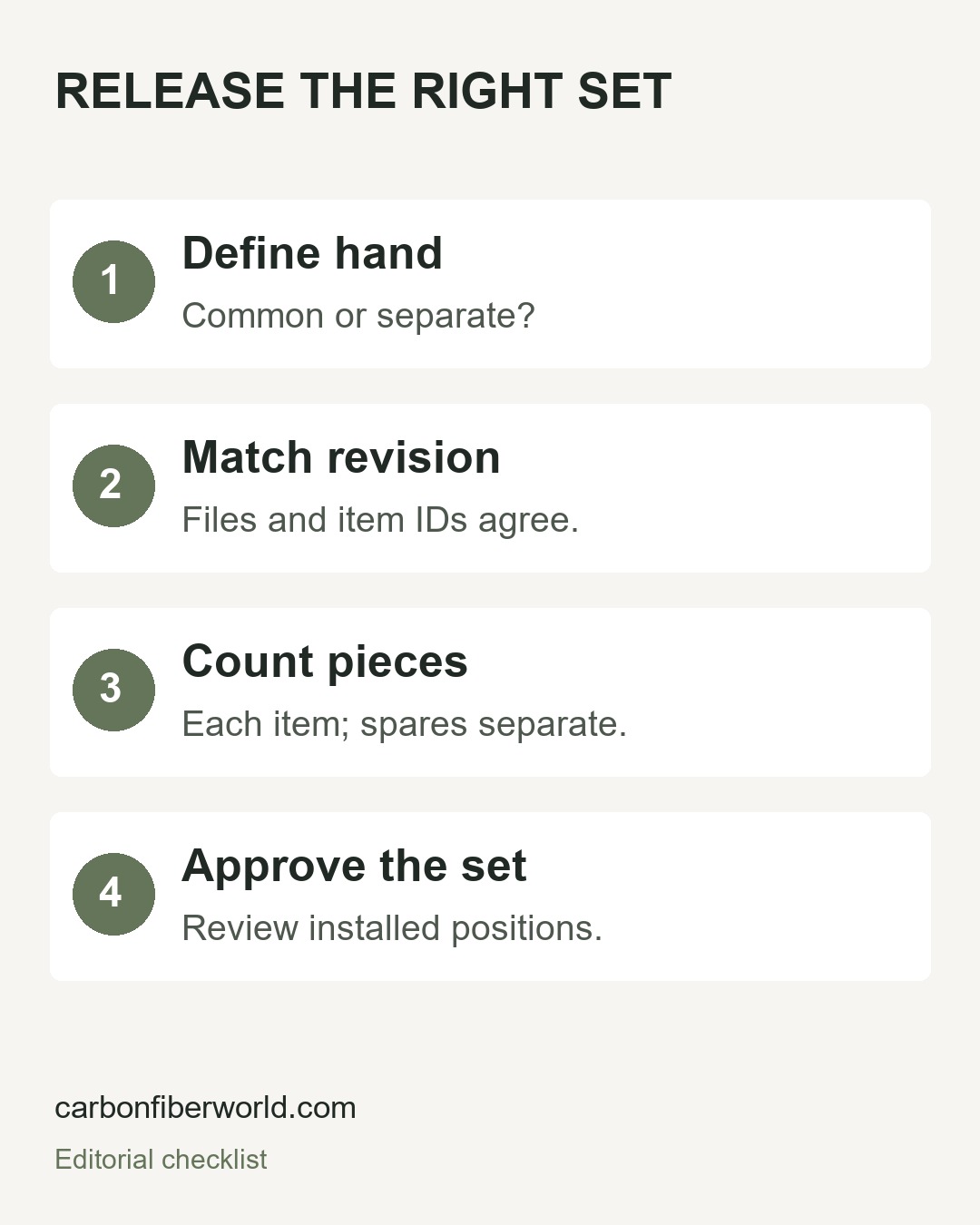
This original editorial worksheet brings the decisions into one handoff. It is not a completed CFW inspection report.
- Common or separate: record the design owner’s decision on whether a common reversible item is permitted. Keep unresolved interchangeability questions open.
- Installed reference: attach the assembly view, viewing direction, approved face and any face-specific requirements.
- Item-to-file mapping: list each ordered part identity, CAD filename, drawing filename and agreed revision together.
- Quantity basis: state pieces of each item per assembly, assembly count and additional spare pieces separately.
- Sample acceptance: identify the sample for each required item and record its installed-orientation review, accepted points and open issues.
- Packing identity: agree the item labels and whether the shipment is grouped by assembly or by component. Tie labels to the same released revision.
Review the complete sample set before release
Check the required counterparts together against the controlled assembly reference. Confirm that the reviewed pieces represent the actual ordered mix and revisions. A correct sample of one item does not approve its counterpart or all pieces in a set. Record which items were reviewed and the scope of approval.
Keep dimensional, appearance and functional acceptance distinct. This identity check does not replace the agreed measurements, material evidence or application validation. If a review changes the required hand, face or feature, resolve the change in the controlled files and order lines before production release.
Prepare a clear CFW enquiry
For a CFW-2795 flat-profile component enquiry, provide the released drawing package, material and thickness requirements, critical features, installed reference view, quantity per identified item and destination. State whether the request covers individual components or defined sets, and identify any spares or requested marking.
Send the part list and drawing-review requirements to CFW so the proposed scope can be assessed. Resolve the identity and quantity basis before comparing an offer or approving a sample.