
Carbon Fiber CNC Nesting: Sheet Area Is Not Part Yield

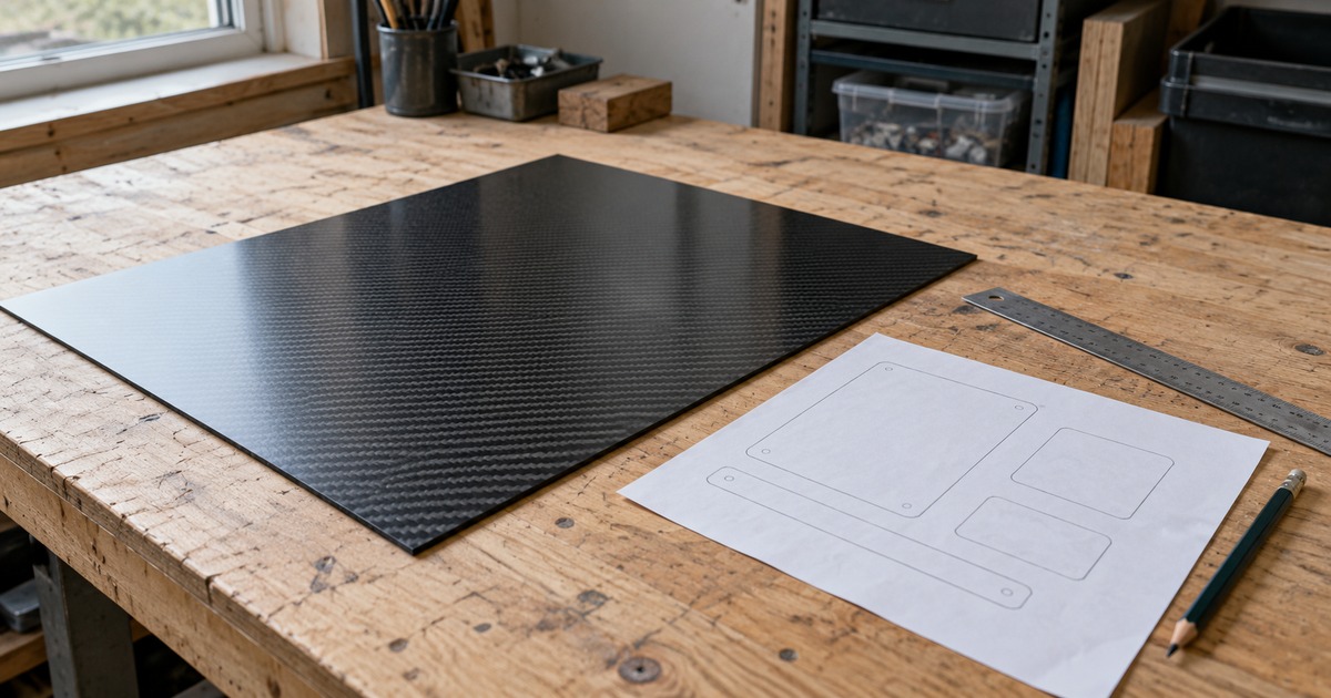
A carbon fiber sheet’s area does not tell you how many finished CNC parts it will produce. A useful nesting plan also needs the actual part profiles, quantities, permitted orientations, spacing and material held out of the cutting area. For a drawing-based order, agree those inputs before treating a sheet calculation as a part-count or price commitment.
Imagine a buyer preparing a batch of flat mounting plates. The drawing is ready, and a spreadsheet divides the sheet area by the area of one plate. The result looks like a convenient purchasing quantity. Yet that division has not shown whether the profiles fit together, whether every plate can face the same way, or which regions must remain available for workholding. The next useful document is a nest with its assumptions, not another decimal place in the spreadsheet.
Start with the part requirement, then define the nesting space
Keep three quantities separate: gross sheet area, an inner planning area after an assumed perimeter setback, and the number of complete acceptable parts in a reviewed layout. The first is a rectangle calculation. The second adds one boundary assumption. The third requires the actual shapes and production constraints.
Before a layout is prepared, make the part definition usable. Supply the drawing revision, thickness requirement, outside profile, holes or slots, required quantities and any edge or face requirements. A compact profile with a cutout should not be treated as a solid bounding rectangle without explaining the approximation. Nor should the area inside that cutout automatically count as recoverable material.
Thickness and laminate requirements remain separate decisions. If they are still open, use the sheet-thickness planning guide and the laminate and drawing guide before asking the nesting layout to resolve them.
Make the layout assumptions visible
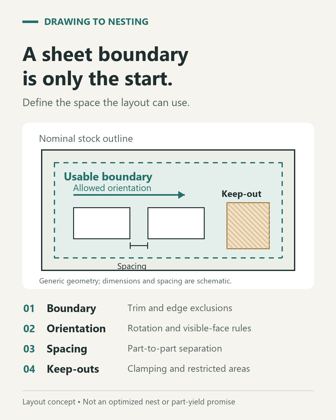
Autodesk’s Fusion nesting reference treats allowable orientations, distance from the outer perimeter, spacing between items and the relationship between the two faces as distinct settings. That distinction is useful when reviewing a supplier’s layout: changing one input can change the arrangement even when the sheet dimensions stay the same.
State whether a visible face must stay upward and whether a direction shown on the drawing restricts rotation. Confirm flip and mirror permissions separately. A flipped part can preserve an outside silhouette while changing which face is presented. These are drawing and production decisions; a tidy screen layout does not settle them.
Ask the person preparing the cutting plan to identify the perimeter restriction, required spacing and any fixture keep-out regions. Do not turn a planning sketch into a recommended machine setting. The actual setup must determine the allowances and workholding approach appropriate to the job.
A worked area example: what a perimeter assumption changes
Consider a hypothetical 400 × 500 mm rectangle. Its gross area is 200,000 mm². If the same setback m is reserved along every edge, the remaining inner rectangle has area (400 − 2m) × (500 − 2m). Dividing that result by 200,000 gives the inner-area percentage below.
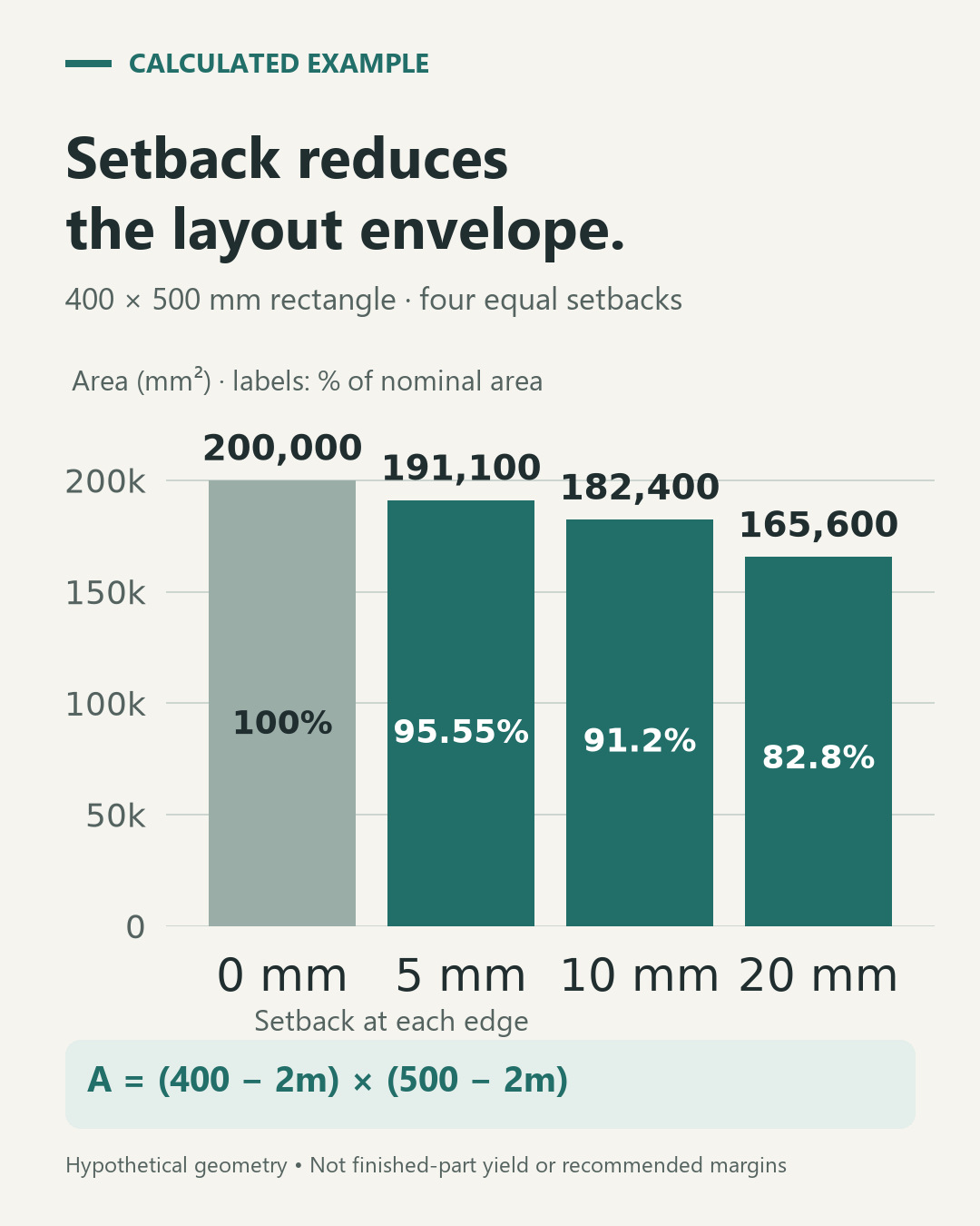
| Assumed setback on each edge | Inner area and share of gross area |
|---|---|
| 0 mm | 200,000 mm² — 100% |
| 5 mm | 191,100 mm² — 95.55% |
| 10 mm | 182,400 mm² — 91.2% |
| 20 mm | 165,600 mm² — 82.8% |
Original geometric calculation for an illustrative rectangle, using an equal setback on all four edges. These are assumed inputs, not recommended margins, available CFW sheet sizes or measured production results. Item spacing, part shapes, orientation and fixture keep-outs are not included.
At the assumed 10 mm setback, the inner rectangle is 380 × 480 mm and retains 91.2% of the original area. This tells the buyer how sensitive the planning area is to that one assumption. It does not establish 91.2% nesting yield, a finished-part quantity or a corresponding cost saving.
To estimate a part count, the next step is to place the actual profiles inside the permitted region with the agreed restrictions. Two jobs can have the same total profile area and still require different arrangements. Narrow features, awkward outlines and orientation limits can leave spaces that another complete part cannot use.
Review the nest before accepting a yield claim
First, check the file revision and quantities. A layout of an earlier profile or an incomplete mix of part numbers answers a different question from the current order. Then check how the drawing’s orientation and face requirements are represented. Finally, ask whether the displayed boundary is the gross sheet or the permitted nesting region.
If a quotation includes a yield percentage, ask what its numerator and denominator represent. It might describe profile area divided by gross sheet area, or refer to another defined basis. It should not be read as the percentage of parts that will pass inspection unless that is explicitly what the evidence measures.
Also ask how unusable remnants, setup pieces and any extra production quantity are handled. Keep the requested delivered quantity distinct from a layout count. A proposed arrangement is a planning record; acceptance still follows the agreed drawing and order requirements.
Use one supplier-handoff record
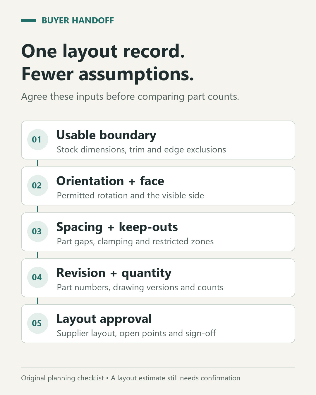
The following record keeps the buyer’s requirements alongside the supplier’s layout assumptions. Fill it in for the actual order and return unresolved entries with the quotation.
- Part definition: part numbers, drawing files and revision; thickness; profiles, holes, slots and edge requirements.
- Quantity: requested delivered quantity for each part, with any proposed extra quantity stated separately.
- Material and faces: agreed laminate requirement, visible face, direction reference and permitted rotation, flip or mirror conditions.
- Layout basis: proposed sheet dimensions, permitted nesting boundary, item spacing and identified keep-out regions.
- Review result: layout revision, complete-part counts and the definition of any reported area or yield figure.
- Commercial handoff: quotation scope, unresolved exceptions, destination and required delivery timing.
For custom carbon fiber shaped parts, send the drawing and revision, thickness, quantities, face or direction requirements, destination and timeline. Include an existing layout if you have one, with its assumptions. Contact CFW to discuss the drawing-based requirement and request a quotation.
Editorial planning guide. The numerical example is an independently calculated area comparison, not a machining test or a confirmed production nest.